Container designs


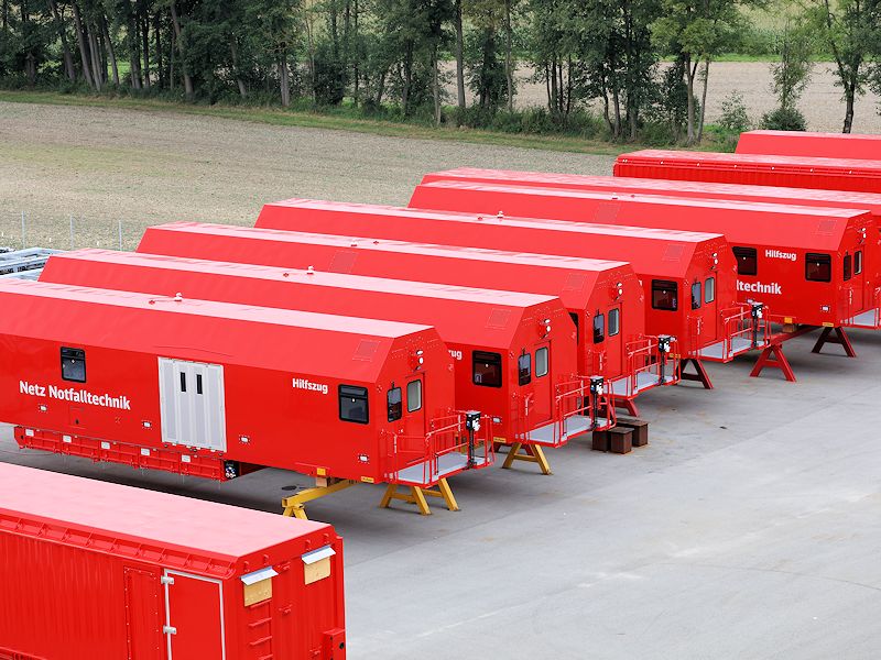
YÖRG – Modules


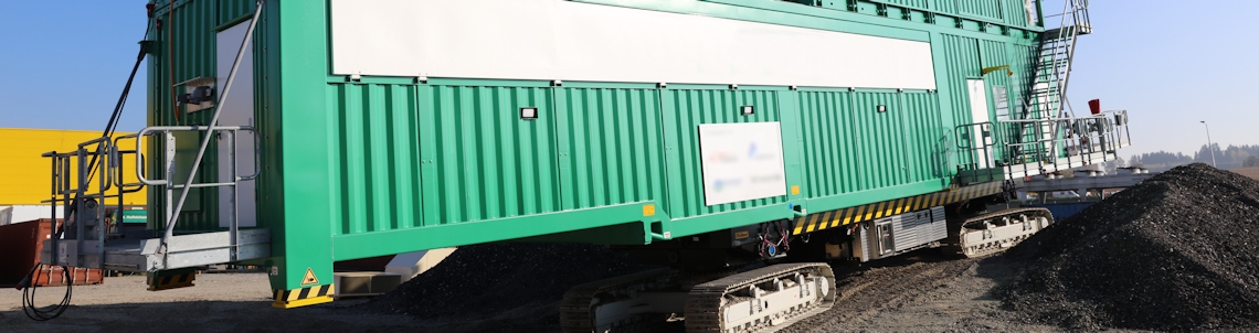
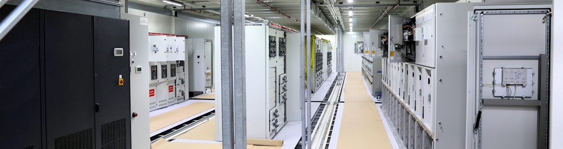
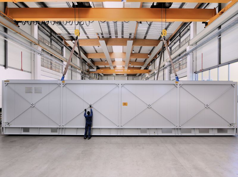
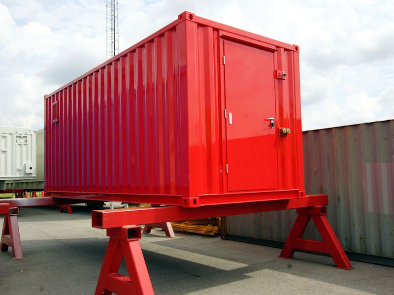
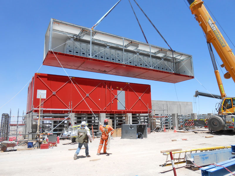
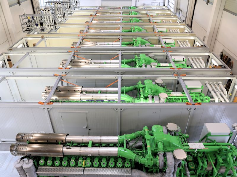
The container modules are designed so that the container bonnet can be unscrewed from the base frame at any time and anywhere. In this way the equipment to be installed can be incorporated quickly and safely.
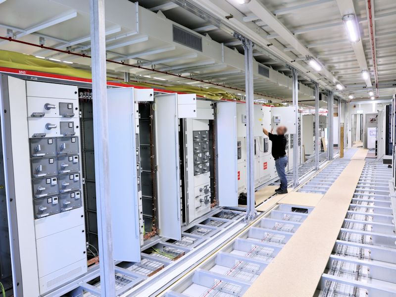
In order to design the cable guide within a module easily and flexibly, there are various concepts with various heights of cable floors.
The requirements for the floor frame are adjusted the customer needs.
| Technical data | YÖRG light | YÖRG standard | YÖRG plus |
|---|---|---|---|
| Length (max.) | 10000 mm | 18000 mm | 25000 mm |
| Width (max.) | 3200 mm | 4000 mm | 5000 mm |
| Height (max.) | 4200 mm | 4200 mm | 4200 mm |
| Payload | 10 tons | 20 tons | 60 tons |
| Traffic load | 250 kg/m² | 500 kg/m² | 1000 kg/m² |
| Cable floor (Height/cross member) | 160 mm | 160 mm | 350 mm |
| Hood | Container hood is removable, this enables easy installation of the equipment | ||
| Walls/roof | Insulation either with PUR hard foam (CFC-free) or mineral wool | ||
| Doors | Panic lock with push button/push button or bracket/push button | ||
| Floor | Double floor prefabricated in the grid dimension 600 x 600 mm/screen printing floor/sheet metal floor/trapezoidal sheet metal floor | ||
| Corrosion protection | The whole steel construction is hot dip galvanized in accordance with EN ISO 1461. The thin sheets in the sandwich elements are strip galvanised. Varnishing according to EN ISO 12944-5 |
||
| Flammability class | according to EN 13501 resp. DIN 4102 | ||
| Fire resistance class | REI 30 up to REI 120 | ||
| Air conditioning and ventilation | Adjusted to environmental conditions and requirement | ||
| Foundation/anchoring | Installation on point, strip or plate foundation made of concrete and/or steel construction. Weld or screw to foundation. | ||
| Earthing/Potential equalisation | 4 connection possibilities are available on container corners for earthing systems/earthing system in the cable floor (copper bars 50 x 5 mm) for potential equalisation of the built-in equipment, detailed execution customer specific | ||
Possible options
- Removable front wall
- Removable side wall
- Over pressure unit
- Dirt barrier
- Large-scale installation
- Pressure relief opening
- Maintenance opening
- Fire alarm
- Fire extinguisher
- Safety lighting
- Stages and steps
- Steel structures and/or substructures
- Shock indicators
- Removable roof
- Lightning protection
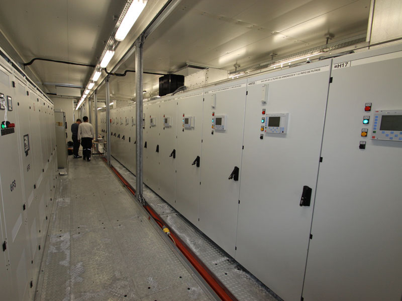
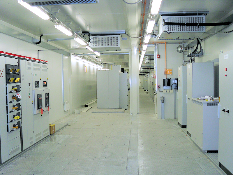
- Integration of control panels
- Integration of transformers
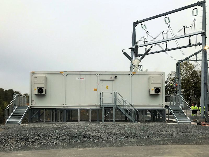
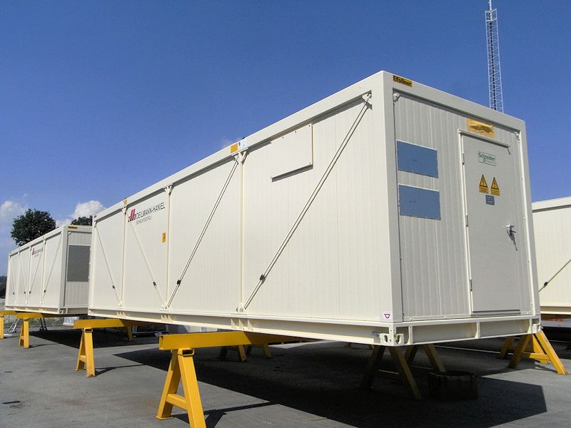
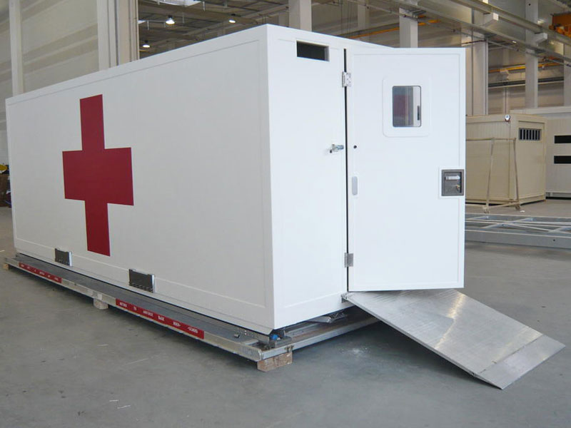
GEORG – Modules


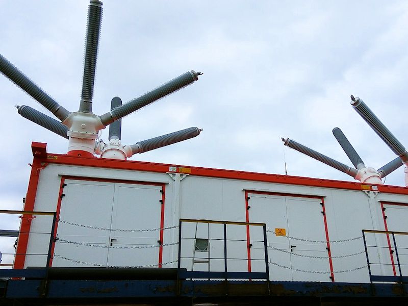
The container modules are constructed in such a way that the container hood can be unscrewed from the base frame anytime and anywhere. The equipment to be built can be incorporated securely and without problems.
In order to design the cable guide within a module easily and flexibly, there are various concepts with various heights of cable floors.
The requirements for the floor frame are adjusted to customer needs.
| Technical data | |
|---|---|
| Length (max.) | 25000 mm |
| Width (max.) | 4000 mm |
| Height (max.) | 4200 mm |
| Payload | up to 60 tons |
| Bear load | 500 kg/m² |
| Cable floor (Height/cross member) | up to 1000 mm |
| Hood | Container hood is removable, this enables easy installation of the installation equipment |
| Walls/roof | Insulation either with PUR hard foam (CFC-free) or mineral wool |
| Doors | Panic lock with push button/push button or bracket/push button |
| Floor | Double floor prefabricated in the grid dimension 600 x 600 mm/screen printing floor/sheet metal floor/trapezoidal sheet metal floor |
| Corrosion protection | The whole steel construction is hot dip galvanized in accordance with EN ISO 1461. The thin sheets in the sandwich elements are strip galvanised. Varnishing according to EN ISO 12944-5 |
| Flammability class | according to EN 13501 resp. DIN 4102 |
| Fire resistance class | REI 30 up to REI 120 |
| Air conditioning and ventilation | Adapted to environmental conditions and requirements |
| Foundation/anchoring | Installation on point, strip or plate foundation made of concrete and/or steel construction. Weld or screw onto the foundation. |
| Earthing/Potential equalisation | 4 connection possibilities are available on container corners for earthing systems/earthing system in the cable floor (copper bars 50 x 5 mm) for potential equalisation of the built-in equipment, detailed execution customer specific |
Possible options
- Removable front wall
- Removable side wall
- Over pressure unit
- Dirt barrier
- Large-scale installation
- Pressure relief opening
- Maintenance opening
- Fire alarm
- Fire extinguisher
- Safety lighting
- Stages and steps
- Steel structures and/or substructures
- Shock indicators
- Removable roof
- Lightning protection
- Integration of control panels
- Integration of transformers
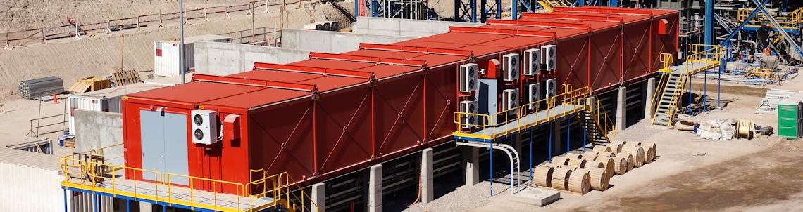
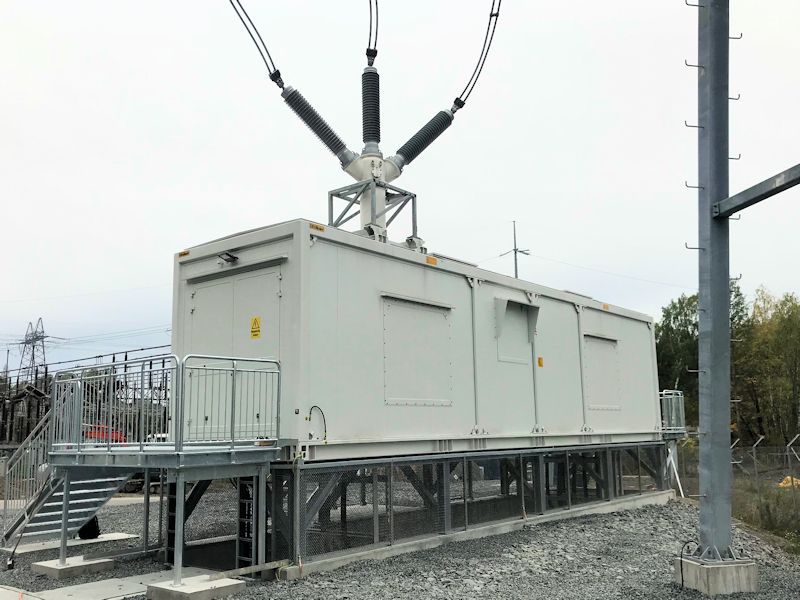
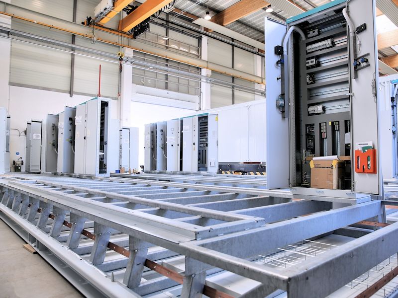
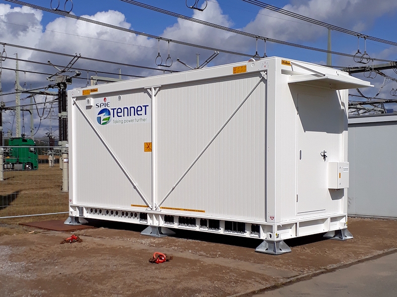
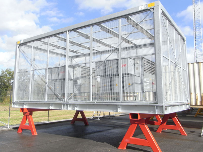
BB – Modules (sheet metal design)


The containers are designed for heavy loads, the container hood can either be unscrewed from or is firmly welded to the floor frame. The walls consist of trapezoid metal sheet and can be insulated with panel plates.
In order to design the cable guide within a module easily and flexibly, there are various concepts with various heights of cable floors.
The requirements for the floor frame are adjusted to customer needs.
| Technical data | |
|---|---|
| Length (max.) | 25000 mm |
| Width (max.) | 4500 mm |
| Height (max.) | 4200 mm |
| Payload | up to 60 tons |
| Traffic load | 500 kg/m² |
| Cable floor (Height/cross member) | up to 800 mm |
| Hood | The container hood is firmly welded |
| Walls/roof | Insulation either with PUR hard foam (CFC-free) or mineral wool |
| Doors | Panic lock with push button/push button or bracket/push button |
| Floor | Double floor prefabricated in the grid dimension 600 x 600 mm/screen printing floor/sheet metal floor/trapezoidal sheet metal floor |
| Corrosion protection | Steel structure sandblasted to EN ISO 8501-1 and painted to EN ISO 12944-5. Inside the sandwich panels are galvanized. |
| Flammability class | according to EN 13501 resp. DIN 4102 |
| Fire resistance class | REI 30 up to REI 120 |
| Air conditioning and ventilation | Adjusted to environmental conditions and requirements |
| Foundation/anchoring | Installation on point, strip or plate foundation made of concrete and/or steel construction. Weld or screw onto the foundation. |
| Earthing/Potential equalisation | 4 connection possibilities are available on container corners for earthing systems/earthing system in the cable floor (copper bars 50 x 5 mm) for potential equalisation of the built-in equipment, detailed execution customer specific |
Possible options
- Removable front wall
- Removable side wall
- Over pressure unit
- Dirt barrier
- Large-scale installation
- Pressure relief opening
- Maintenance opening
- Fire alarm
- Fire extinguisher
- Safety lighting
- Stages and steps
- Steel structures and/or substructures
- Shock indicators
- Removable roof
- Lightning protection
- Integration of control panels
- Integration of transformers
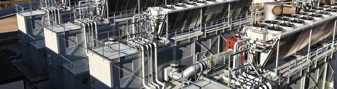
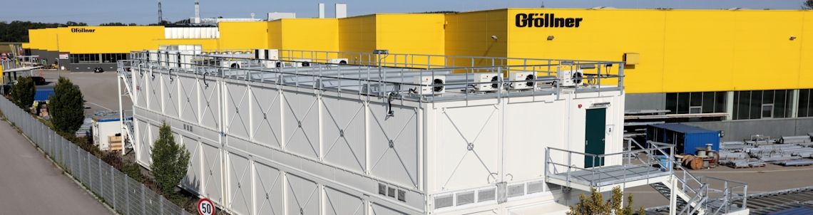
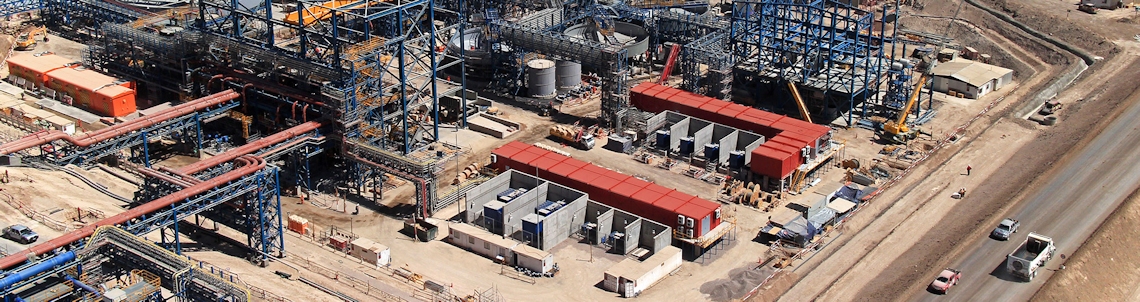
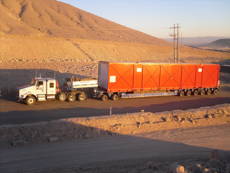
Large-scale buildings
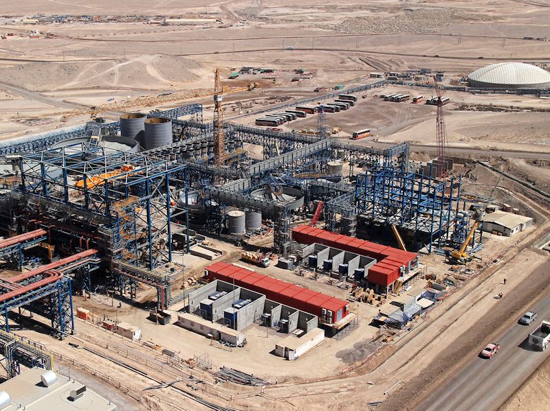


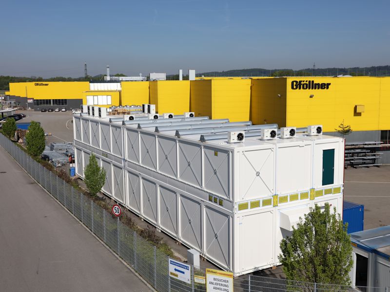

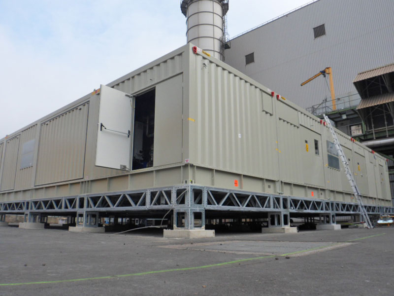
The container module can be coupled to make block units.
Special concepts for demanding projects in container construction!


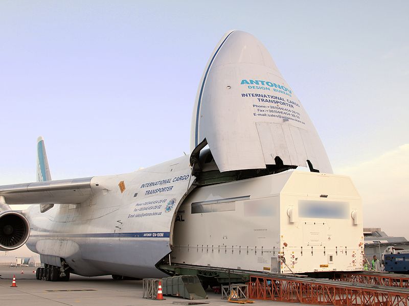
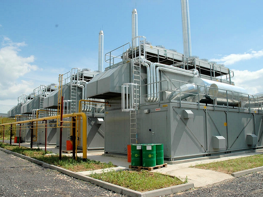


The high performance of the company is evidenced by the demanding container building projects in various areas of use. Our engineers are happy to help you with the implementation of your company specific requirements for mobile room solutions.
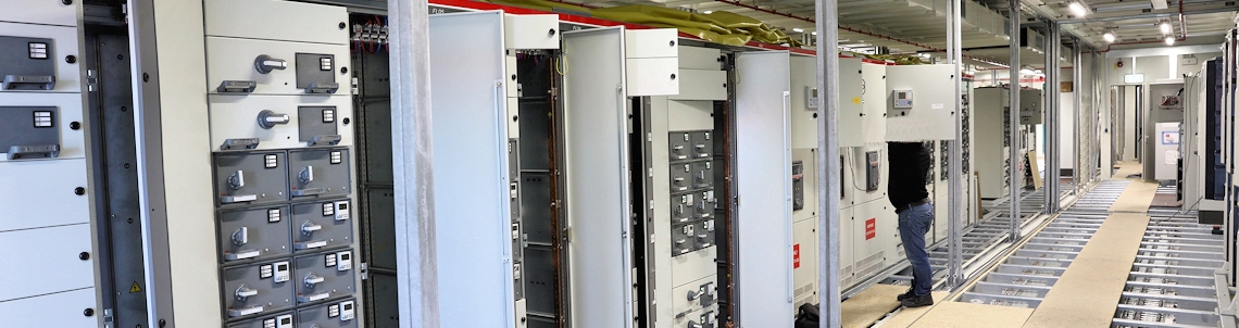
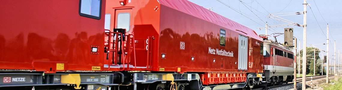
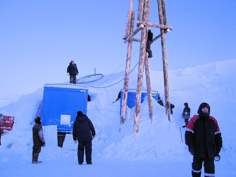
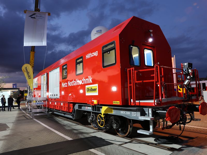
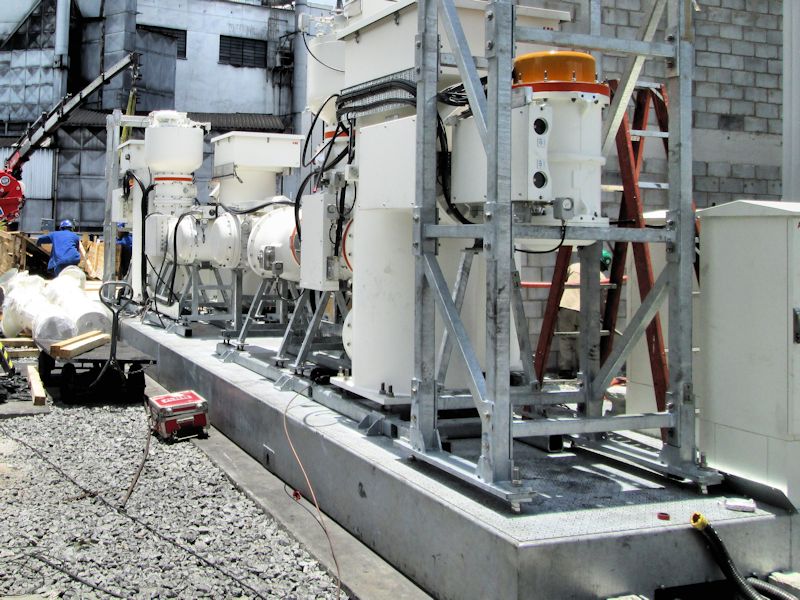
Transmission- & Monitoring stations
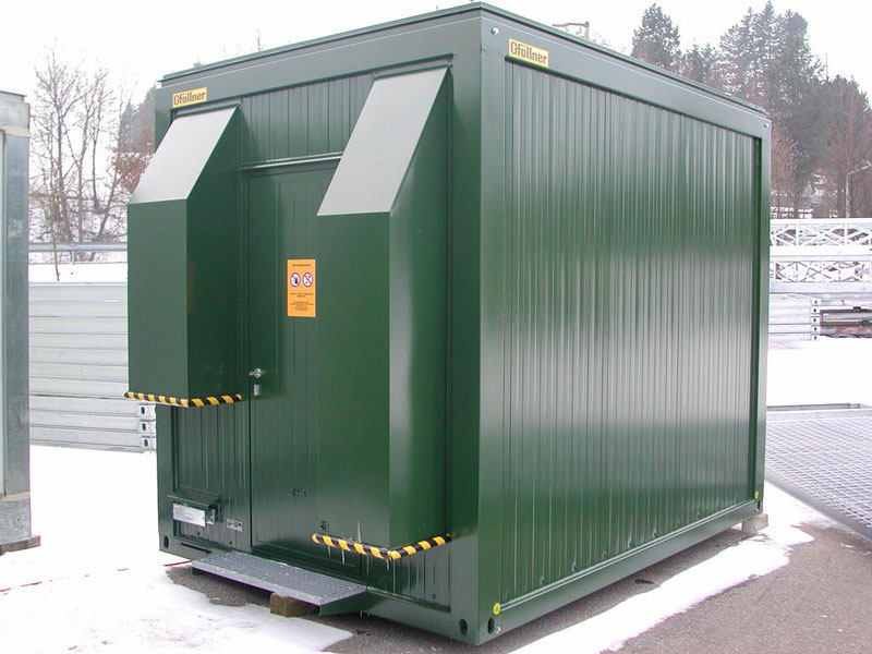


The transmission and monitoring stations were specifically developed for data transmission network construction and air quality monitoring requirements. Thanks to the possibility of positioning all parts individually, they can be adapted for any location in an easy and affordable way .
Important to note:
An optional perimeter cable tray is available for guiding the cables.
The pre-installation of light, maintenance sockets, door contacts, right up to specially adapted sub-distribution boards is possible depending on the project and is often used by our clients with a high level of satisfaction.
The interior space can be designed individually. Thanks to the high load-bearing capacity of the floor, even heavy racks or battery racks for a UPS system can be installed.
Ventilation or air-conditioning systems can be dimensioned and installed if required.
A very space-saving version for mast mounting offers the possibility of placing the transmission mast on the roof of the module. This can be achieved with ease thanks to the optionally provided corner reinforcements.
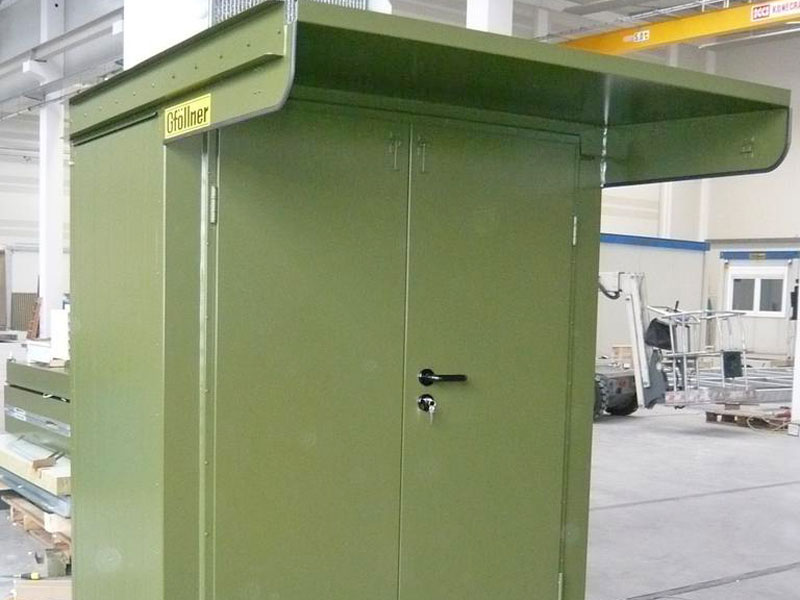
The transmission and monitoring stations can also be designed as technical rooms. Openings for supply and exhaust air can be added individually. The antennae cables are usually guided via a 6x1 reinforced steel frame. The position can be determined individually depending on the mast position.
| Technical data | |
|---|---|
| External dimensions(L x B x H) | 2900 x 2340 x 2780 mm or customized |
| Interior dimensions(L x B x H) | 2640 x 2070 x 2500 mm or customized |
| Own weight | approx. 1,6 to |
| Payload | 500 kg/m² |
| Ice shedding protection | 2 mm aluminum tank |
| Rain water drain | One-sided definable |
| Walls/roof | Insulation either with rigid polyurethane foam (CFC-free) or mineral wool, e.g. 100mm rock wool panel U-value 0,46 W / m²K |
| Doors | For example: EI 90 2000 x 800 Canopy 410x1000 mm Foot scraper 300x1000 |
| Corrosion protection | Floor hot-dip galvanized Frame galvanized Painting with 50μm RAL color as desired |
| Flammability class | according to EN 13501 resp. DIN 4102 |
| Fire resistance class | REI 30 up to REI 180 |
| Air conditioning and ventilation | Optional on request |
| Foundation/anchoring | Foundation only needed at the corners, fixing with four load anchors M12. |
| Earthing/Potential equalisation | 4 connection possibilities are available on container corners for earthing systems |